
- Microcoil heaters
-
Cartridge heaters
 Without thermocouple With thermocouple Special executions
-
Band heaters
Flat Mica Heaters Nozzle heater Mica heat band heaters Ceramic band heaters
-
Thermocouples
Thermocouples model TC-11 Thermocouples Model TC5 Thermocouples model TC8 Model TC-1 (anchor point) Model TC-3
- Tubular heaters
- Spiral heaters
- Infrared heaters
- Drum heaters
Special executions

The totality of the cartridge heaters can be customized according to the customer's requirements, it may be that the cable exit does not coincide with the angle at which the main connections are located, so that we can direct the output of the heater cables towards the connector, by means of the flexible exit of the cables of the same interior of the heating element or with an extension of the tube of the same to 90 º
As another option, it is sometimes necessary to protect the cabling of the cartridges by means of a metallic mesh that insulates them from chafing due to the movement of said element when it is introduced in movable parts of the machine (such as jaws or during the opening and closing of molds). ).
We can also adapt a flexible metal tube to protect the heating element from the water, also applying in its termination, not a cement base, but a water-proff seal that isolates it electrically from very humid environments.
In the same way we can also manufacture them in different heated zones for packaging and packaging or by applying a fitting or finish for a better fixation in the workplace.
SPECIAL TYPES
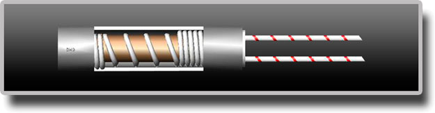
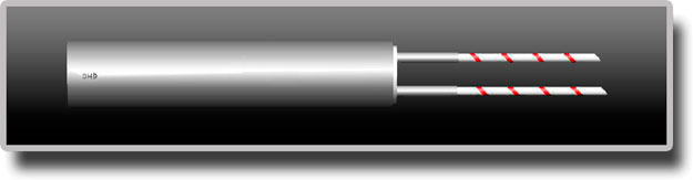
Type HFLEX with galvanized steel leads protection
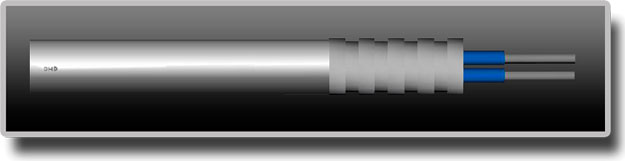
Type HMB metal braided over fibreglass nickel leads.

Type H90 ANGLE 90º EXIT

|
Ø
|
1/4"-6,5
|
8
|
3/8"-10
|
2"-12,5
|
5/8"-16
|
3/4"-20
|
|
H
|
6,5 | 8 | 10 | 12,5 | 16 | 20 |
|
L
|
21 | 23 | 25 | 30 | 35 | 40 |

|
Ø
|
8
|
3/8"-10
|
2"-12,5
|
5/8"-16
|
3/4"-20
|
|
H
|
6,5 | 8,5 | 11 | 14 | 18 |
|
L
|
8 | 10 | 13 | 16 | 18 |
Type HP high temp seiled, waterproof 350º working temp

Type HA, .different heating zones, different power zones
Type Hp, nickel pins exit welded fibreglass leads
Type HB. Fitted in stainless steel or brass

|
|
Type HF, stainless steel flange

|
0
|
1/4"-6,5
|
8
|
3/8"-10
|
2"-12,5
|
5/8"-16
|
3/4"-20
|
|
A
|
18 | 18 | 27 | 27 | 33 | 33 |
|
B
|
13 | 13 | 20 | 20 | 25 | 25 |
|
C
|
2,2 | 2,2 | 3,2 | 3,2 | 3,2 | 3,2 |
CARTRIDGE HEATER DIAMETER 4

|
CATRIDGE DIAMETER
|
6,5
|
8
|
10
|
12,5
|
16
|
20
|
|
DIAMETER TOLERANCE
|
0/-0,1 | |||||
|
LENGHT TOLERANCE
|
±2% | |||||
|
WATTAGE
|
5%-10% | |||||
|
RESISTANCE
|
5%+10% | |||||
TECHNICAL DATA
|
Diameter (metric & imperial sizes) and Tollerances
|
||||||||||
|
Ø
|
6,5
|
8
|
10
|
12,5
|
16
|
20
|
1/4"
|
3/8"
|
1/2"
|
5/8"
|
|
Tollerance
|
-0,03
|
-0,04
|
-0,04
|
-0,05
|
-0,05
|
-0,06
|
-0,03
|
-0,04
|
-0,05
|
-0,05
|
|
-0,05
|
-0,06
|
-0,07
|
-0,08
|
-0,08
|
-0,1
|
-0,05
|
-0,07
|
-0,08
|
-0,05
|
|
|
Length Tollerance
|
Relative ±1,5%
|
|||||||||
|
Cold insolution Resistance 500 V-DC
|
Absolute ±1mm (minimum)
|
|||||||||
|
Dielectric Strength
|
≥ 10 MΩ
|
|||||||||
|
Maximum leakage current (cold)
|
≤ 0,5 mA
|
|||||||||
|
Cold Wattage Tollerance
|
±10%
|
|||||||||
|
Maximum power Density
|
50 W/cm2
|
|||||||||
|
Unheated Zones Length
|
Cables Zone from 5 to 15 mm
|
|||||||||
|
Botton Disc Zone from 5 to 10 mm
|
||||||||||
|
Maximum Working Temperature
|
700ºC on the external sheath
|
|||||||||